 Milwaukee Eight® - From EFI To Carburetor
- A Brand New World For The Brave -
Already in trouble or just curious ?
On this page we will show you how to upgrade your Milwaukee-Eight® motorcycle to carburetor and completely eliminate the stock electric CAN-Bus system.
In other words .. we're going back to the 1980's .. the M8 engine somehow looks like an EVO on steroids anyway ...
NOTE: The modification shown on this website may not be street legal in some states or countries. If in doubt, check out your local police station. You may also lose your original HD® warranty. Basic tools and experience are required for this modification, and it is carried out at your own responisbility!
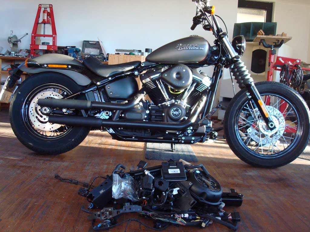
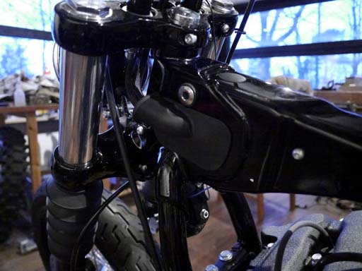
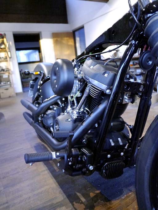
Let's start with a swift look at what we want to accomplish: the M8 liberated, notice rubble in front removed from bike:
This tutorial is very similar to the Twincam and Sportster upgrade instructions you may already know, the main differences are:
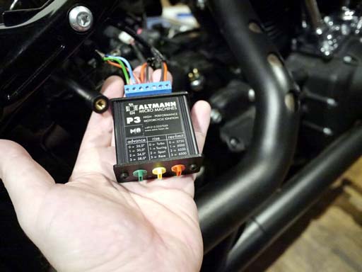
Instead of the AMM-P3 ignition (for Twincam, '04-up Sportster, late EVO), you need the AMM-P3M8 ignition which is made specifically for the Milwaukee-Eight engine!
The AMM-P3M8 for Milwaukee-Eight engines can be ordered by clicking the paypal button below. Prices include worldwide shipping.
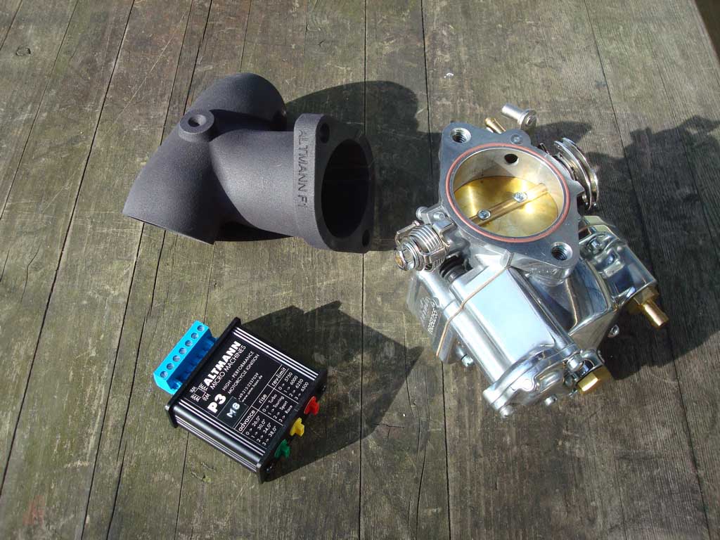
You also need one of our AMM-F1 / F2 manifolds and - of course - a carburetor.
Choice of carbs is limited to what fits between the big M8 cylinder heads.
We offer the following manifolds:
AMM-F1 fits S&S Super-G, S&S Super-D as well as Ultima-R1. This is the big manifold.
AMM-F2 fits S&S Super-E, S&S Super-B and Ultima-R2. This is the slightly smaller manifold.
Note: These manifolds do not fit VVT heads!
Please order the matching manifold for the carburetor of your choice.
Another difference in this M8 EFI to carb upgrade tutorial is that we totally get rid of the stock electric system.
Motivation for this modification
The stock M8 electrics is a complex and centralized computer system with CAN-Bus as a communications-device between operating units.
- These units are:
- The BCM (body control module) which is the big-boss of this system distributing power to all subsystems, lights, horn, etc.
- The ECM (engine control module) which operates the engine fuel-supply, air-supply and ignition.
- The EHCU (electric hydraulic control unit) - if fitted - to operate the ABS brake.
- The right and left handlebar controls that pick up your switch-button commands and send them out via CAN-Bus to the BCM.
- The speedomenter that receives CAN-bus commands and displays them as speed, rpm, etc.
- The BCM (body control module) which is the big-boss of this system distributing power to all subsystems, lights, horn, etc.
As inherent in all centralized systems, if they fail, they have a strong tendency to fail .. completely.
Given the complexity of the stock electric system, the sheer number of wires and control boxes (often buried inside the bike hidden from easy access), as well as the fact that only the authorized dealer has extended access to diagnosis- and software-tools - make this a very delicate and expensive motorcycle with respect to the service costs that lie ahead of you - or already behind you.
- Would it be already considered conspiratorial thinking, when just wondering why something like a simple wire and a switch to power a headlamp is replaced by an elaborate computer communications system for no other reason than stopping you from fixing the simplest of things, effectively turning you into a slave of your own machine ? Oh wait, now don't tell us you've seen this happening all around with other motorcycles and your cars too ... Does something bad become less bad, just because it seems to be happening everywhere ?
Upgrading your Milwaukee-Eight ® engine to carburetor using the AMM-P3M8 ignition system will fully unleash your engine's performance by taking away the limitations built into the OE injection system.
Your bike will go faster (no speed limit) with smoother performance. You will have great starting and idle, immediate and unhindered throttle response.
- Wouldn't it be easier to just upgrade to carb while keeping most parts of the stock electric system, as shown in the Twincam and Sportster upgrade instructions ? Yes, it would be easier and we tried that first, however the current M8 electric systems programming does not allow for it: As soon as the throttle body is disconnected two things happen: the BCM blocks the starter motor and illuminates all the leds in the speedo blocking their normal function too. Overriding the starter motor control by a separate switch and relay makes the engine start and run excellent on carb and P3M8 ignition, however after a 15 minutes ride a third thing happens: as soon as the bike comes to a stop, the BCM shuts down current to all systems - lights, flasher, horn, speedo, ignition power - all go off. As mentioned before, its a centralized system and sadly one that is run very poorly. Whenever a system becomes rotten beyond the point that any and all participation in it will not enable it to recover, there is only one way out and that is to get rid of it - and get rid of it thoroughly, completely and definitely!
So .. let's strip her down ..
Remove seat and side-covers.
Turn ignition on with fob present (your last use of the fob ;-) and pull main fuse. Disconnect battery minus wire, battery plus wire and remove battery from bike. Remove fuel-tank and rear fender. Remove air-filter, throttle body and manifold. Install AMM-manifold, carburetor.
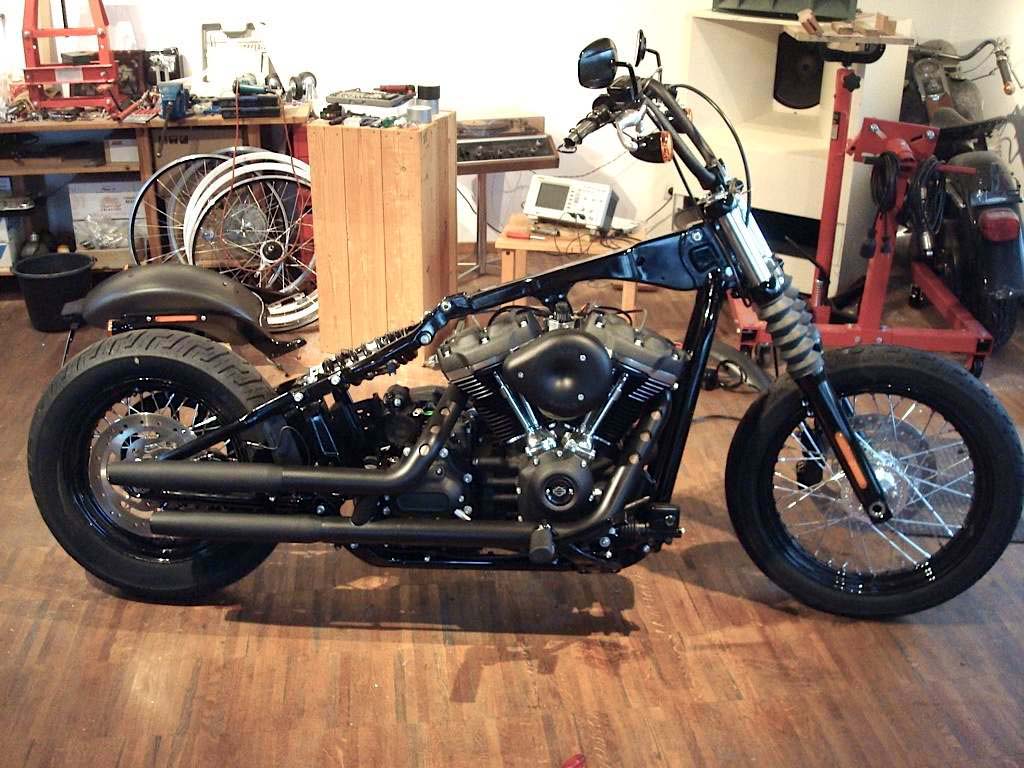
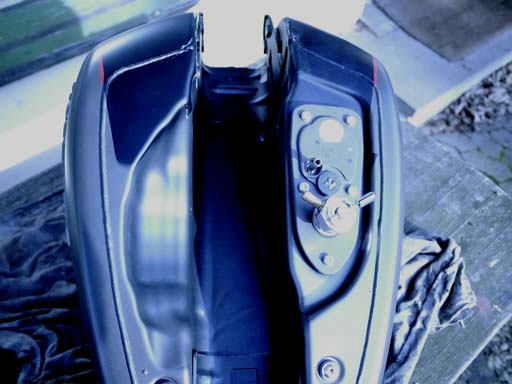
Remove entire electric system, all boxes, all wiring, handlebar controls, speedometer, throttle potentiometer, etc. (keep wiring on rear fender as-is, keep voltage regulator at front of bike and keep decompression release valves). Install old-style risers and handle-bar clamp (they fit the M8 triple trees).
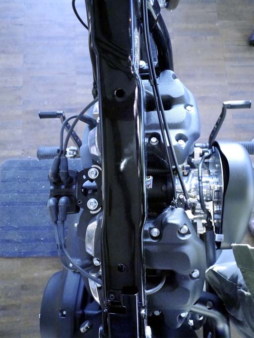
After stripping, your bike should look somehow like this:
In order to build up the new electric system from scratch, we need a couple things.
First, we need a plan, it's here (this plan is also included in the AMM-P3M8 ignition's owner's manual which you can download here).
This plan is an example of one of the simplest-possible automotive electric systems. We will further simplify things later in this tutorial (using only 2 sub-fuses and even getting rid of the starter relay).
- If you have never read a wiring diagram, this is your chance. Take some time looking at it and understanding it. Technically it all goes like this: Current flows from battery plus - to main fuse (40A) - to ignition switch - to sub-fuse (10A or 15A) - to some kind of switch - to some kind of consumer (lights, brake, flasher, horn, ignition, etc.) - and back to ground, which is battery minus. Many of you already have installed electric systems from scratch on a couple of bikes and have their own ideas of how to run and switch their wiring. This plan is just a simple idea to get those of you started who need exactly this: a simple idea.
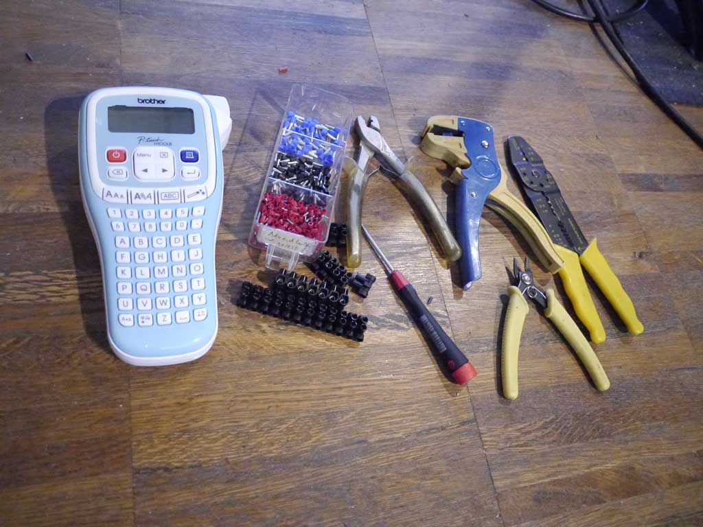
Second, we need some tools, as shown below:
- The black things are screw-type connectors (we call them Luesterklemmen). They are used to connect wires together. The small red, black and blue thingy's are called wire-end ferrules. These are put at the end of a wire (with stripped isolation) and then crimped with the pliers beneath, giving an airtight connection that will work flawlessly for decades to come. You also need rolls of wire with different colors (not shown here), on this bike we use red (mostly for power), black (mostly for ground), green and blue (for different uses). The funky blue device on the left is an inexpensive label-printer, used to take out the guesswork out of your (of our own) wiring.
Our simplistic electric system consists of the following parts:
- Main power line: from regulator to electric starter, battery, fuses and ignition switch
- Front-harness: from handlebar to flashers, horn, lights, brake, ignition
- Rear-harness: to brake-light, rear flashers, back-light
- Ignition harness: ignition coil and crank-sensor
- Front-harness: from handlebar to flashers, horn, lights, brake, ignition
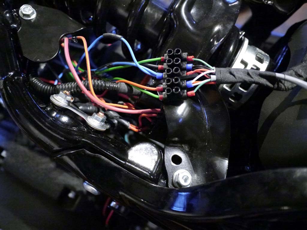
Main Power Line
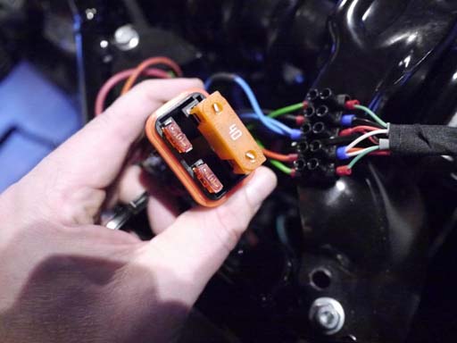
There is one part of the original wiring that we keep using, which is the main power line. It comes from the regulator located at front of engine, goes along the right side frame bottom to the electric starter, battery and fuse-box. The main power-line also contains wires for the rear-brake-switch and the crank-sensor. Shown below the fuse box again located behind left side-cover. The small sub-fuses are of 10Amp rating, one for ignition and the other for the rest (lights, flasher, brake-lights, horn).
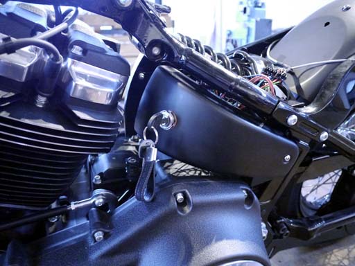
We have located the ignition switch inside the left side-cover. This is a simple 3 position, 3-terminal automotive ignition switch: OFF, ON, START (with return spring). Since this ign. switch has a rugged contact, we can do not need a starter relay: The start-terminal of the ignition switch is connected directly to the starter solenoid, easy.
Handlebar Controls - Front Harness
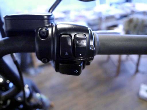
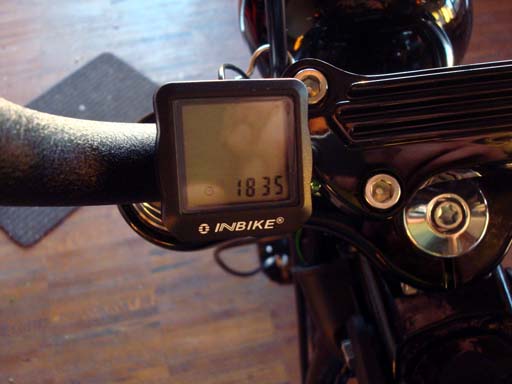
This is the most difficult part of the job ahead, but it is not so difficult after all. You need real-switches in your handle-bar controls, HD® pre CAN-bus switches will do, we found a cheap pair of chinese knockoffs on ebay and hey, they somehow did the job. Bicycle speedo, self-contained and independent from main harness.
Route the wires of the left and right handlebar controls through the inside of the handlebar to the left side of the frame, where you have the big electric cavity. Here you see how the label-printer comes in handy, every wire's got its own neat label with its function printed in plain english, i.e. FLASH R, FLASH L, HI BEAM, LO BEAM, BRAKE, IGN +, START, COIL +, HORN, and so on ... The labels will help you (or somebody else) to understand your wiring even years later, so if there ever should occur the tiniest of problems, it can be rectified easily and swiftly.
The silver round thing hanging at the bottom is the 2-terminal flasher-relay and it works perfectly with the rear LED lights, as long as the front lights are real-bulbs, which they are. The 2 orange things on the right are connectors that are used to distribute Ground and Lights + power.
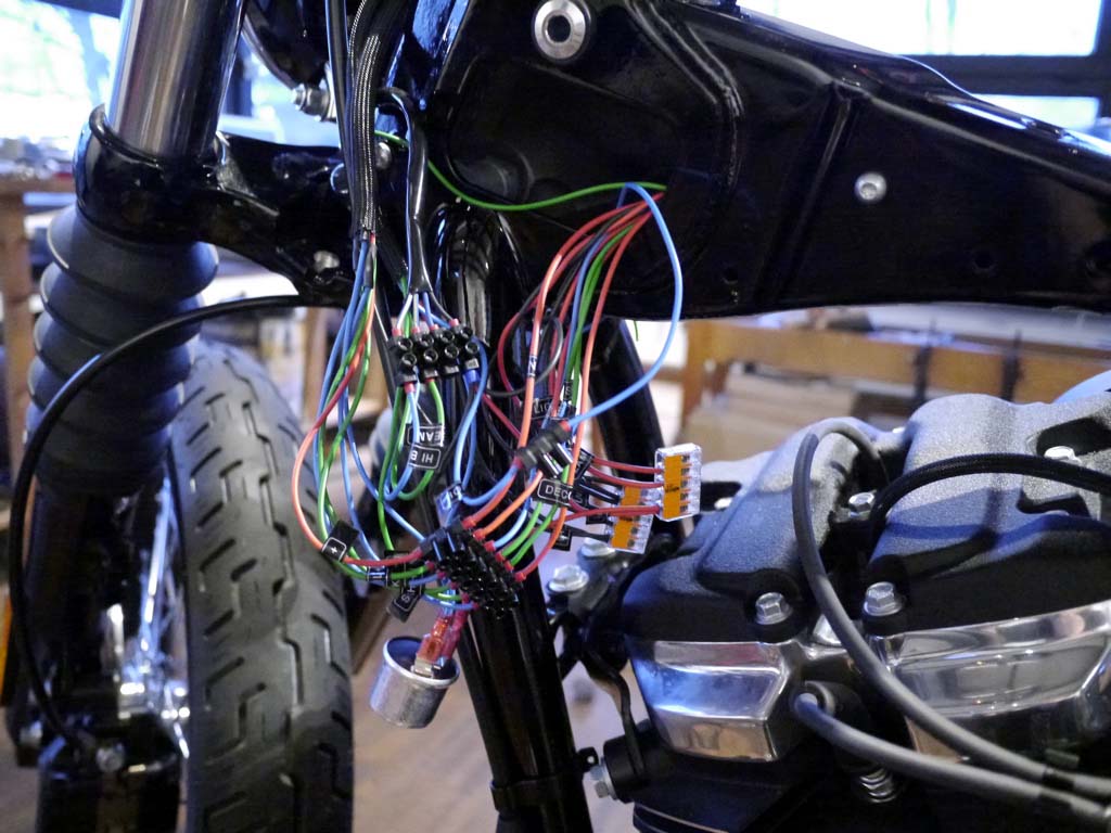
The above may look like much chaos but actually, it is not. Once tested for function, all that is tucked away into the frame and gone from sight.
There are only 7 wires going from the seat area towards the front harness (LIGHTS +, IGN +, RUN, FLASH L, FLASH R, BRAKE, GROUND), this is the left loom. The right loom is the 3 wires that go to the ignition coil.
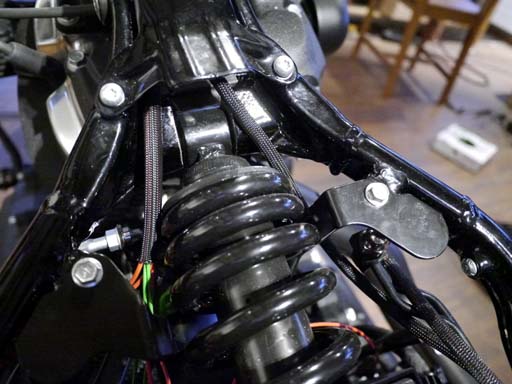
Rear Harness
Here we have not much to do. Install rear-fender and connect license plate light, back-light, flasher, brake-light. The color-codes on the M8 Street-Bob are as you might guess: green for right and left flasher, black for ground, white for back light and red for brake light. Licence plate illumination is 2 black wires with no polarity, since its a normal light-bulb. On this picture you also see the main ground connection to the frame. All ground goes here!
Ignition Harness
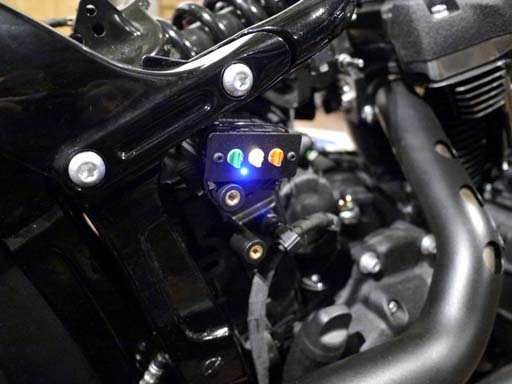
Now the fun part. Locate nice place for the AMM-P3M8 ignition, i.e. behind right side cover. In our electric system the ignition has its own fuse and is therefore independent of the remaining system.
Make connections to crank-sensor, ignition-coil and power according to the AMM-P3M8 user's manual .. Done :-)
The AMM-P3M8 features a removable blue connector. Should you want to immobilize your bike, just pull the connector and put the P3M8 module in your pocket.
Hey .. that was the complete electric system ...
yes, it is some work, but ... now it's YOU, who is .. IN CONTROL !
Tank
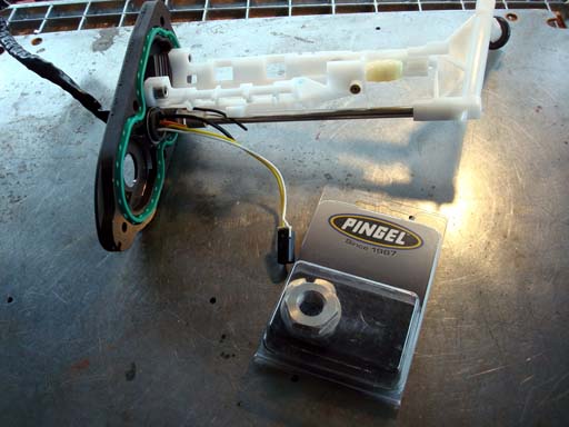
Just like in every EFI to carb upgrade, we have to do some quick modifications to the fuel-tank. Empty tank and flip it over (stock fuel-cap is not vented and air-tight, so any remains of fuel in tank should not spill when tank is flipped, however ... you check for it, gasoline=flammable!). Remove bottom tank plate and remove from tank.
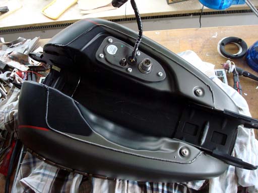
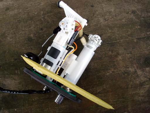
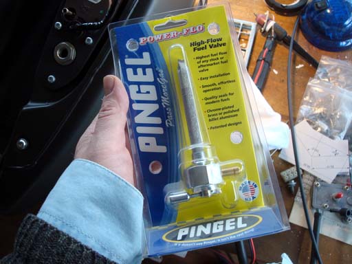
Remove all the plastic and wires from tank-plate. Since the stock fuel-cap is non-venting you need to keep the metal snorkel and it's bottom outlet. If you install a vented fuel-cap, you can remove the snorkel and close the bottom port. You need a petcock (i.e. Pingel) and an adapter that makes the petcock installable in the tank-plate. The Pingel part numbers are #62039 (Carb Conversion Milwaukee-Eight) and 6111-AH (Valve 1/4 NPT Hex). You can order the parts directly from the Pingel-website. Use Teflon-tape on the petcock thread.
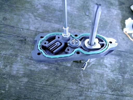
Your tank-plate should now look like this, and is ready to be installed.
Throttle-wires and final check
Install throttle-grip for carb and a set of throttle wires (we're using here those of the 2010 Sportster Iron model). Install fuel-hose with some heat-isolation hose, as it passes close to the front cylinder. We're using the stock screws and rubber-hose for engine venting into air-filter cover. Adjust throttle wires for some slack, install tank, connect fuel-hose to tank. Install seat.
Ready To Go!
Here's a small video of finished bike, doing some minor carb adjustments, enjoy :-)
Odds and Ends
You may have noticed that we got rid of the oil-cooler and lines and for a couple of reasons: Better workability with the wiring and carb installation, gone the ugliness of original oil-cooling contraption, lower oil-temps, more cooling air to cylinders. Passing engine oil through the hottest spot of the cylinder heads may cool the heads a little bit, however the oil will overheat (burn) causing it to degrade in shorter time, risking premature overall engine-wear. Running on carb with correct jetting leads to lower combustion temperatures, compared to EFI. The main reason for this are the continuous air-fuel mixture inherent with carburetion as well as better homogeneity of the mixture itself. This is a test, we are not encouraging you to do the same, if our cylinder heads melt due to overheating, you will read it here first.
The forward foot-controls you see on our bike are made by Thunderbike.
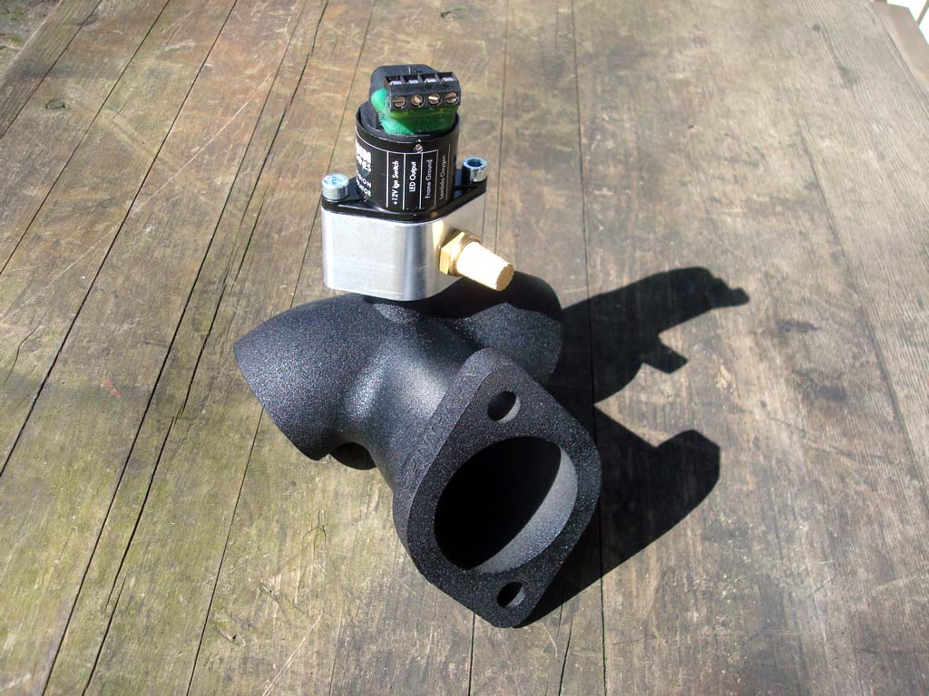
Some of you may have seen a strange thing sitting on top of the manifold. This is the AMM-L1: a oxygen(lambda)-controlled precision air-valve, developed by Altmann in 2005 in order to prove that a carbureted-bike can be as clean (or cleaner) than a fuel-injected bike, which was impressively shown by companies like Saxon motorcycles, Climax motorcycles as well as Zero-Engineering who used the AMM-L1 on their production bikes in order to pass emission-tests.
In this tutorial the AMM-L1 is just used as an optional accessory in order to find the optimum carburetor jetting and setting.
In the above instructions we use the S&S Super-E carburetor with a 0.295 intermediate and 68 main jet.
More Odds and Ends
The decompression valves are not shown in the wiring diagram. That's because we leave them unconnected.
At first we had them connected in parallel to the starter motor. That was a bad idea because, when activated, they lean up the fuel-air mixture causing bad starting behaviour. Leaving them unconnected, we get excellent starts. The AMM-P3M8 fires on the 3rd revolution of the crank, in order to properly synchronize to the engine and avoid back-firing.
You may use a separate button to manually activate the decompression valves (if you think you need them), however on the stock engine, we see no use for those valves.
If you have any questions, feel free to ask.